
Z80 single board CP/M computer "The Bigboard"
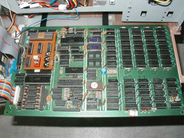
After having seen the ad in BYTE Magazine in 1981, I decided this is my entery into personal computing. The board consisted of an 2,5 MHz Z80 CPU, 64kByte of RAM, video RAM and signal generator, 2 serial ports 2, parallel ports (1 x general purpose, 1 x keyboard), timer/counter, 4 ROM sockets and 8" floppy disk controller.
I had to assemble the board (lots of soldering), built a +5V, +/- 12 V power supply (based on transformes, voltage regulators and capacitors) and bought a B/W (actually black and green) video monitor (National Panasonic H-12504NA; with H-sync, V-sync, video, GND) and two full hight 5 1/4 " MPI floppy disk drives (double side, double density, max. 500kB unformatted). After assembling these bits and pieces I hooked up a serial terminal and then came the great moment of "first time power on".
The board "booted" from the delivered ROM which included a small monitor program (called "PFM") which implemented simple commands like memory display/mofify, I/O read/write, floppy sector read/write and boot.
The board was advertised as "ready to run CP/M". It may have been, if I had 8" floppies properly formatted and loaded with CP/M. But I did not. Luckily, I had access to CP/M object code (CCP, BDOS, BIOS and transient programs) and documentation, and to a Z80 cross assembler and EPROM programming device. This enabled me to write a formatting program for 5 1/4" floppies with 128, 256 and 512 bytes/sector, single and double density, single and double sided.
I had to modify the HW to run CP/M with the 5 1/4" floppy drives: First I built a piggyback board which replaced the WD1771 floppy disk controller by an WD1791 and a separate data separator chip which was able to drive 5 1/4" floppy drives in double density (MMFM encoding). Due to the differences of the 8" and 5 1/4" floppy disk drive connector, I had to partially rewire the connector on the board and added a separate signal (head select), which did not exist on the 8" drives.
I adapted the monitor program to handle the 5 1/4" floppies by properly programming the WD1791 chip and wrote a BIOS based on the monitor. Because the CP/M code I had wa sstored on incompatible media, I wrote two little utilities which read the object code from the memory of one machine and sent it over the serial I/F. On the Bigboard, the received data was written to the floppy disk. In addition, I designed a little bootloader which fitted on the first sector of the floppy disk and loaded the CP/M CCP and BDOS into memory. With all these items, I constructed my first CP/M boot floppy. Then I uploaded the transient programs from another CP/M machine via the serial link and stored them on my CP/M system disk.
To enhance the machine, I replaced the 2,5 MHz Z80 CPU & crystal and related chips (PIO, SIO, CTC) by 4 MHz components and achieved a "performance upgrade". I am still not convinced this was a good idea because during recent test, the machine is freezing after about 20 minutes of operation (memory test). Maybe some parts get to hot due to the higher clock frequency and fail.
Next came a B/W monitor and a parallel keyboard which replaced the serial terminal. My love for electronics is strictly limited to digital parts, so I had a bit of a hard time to adjust the monitor (sweep rate and H/V blank time) to the Bidboard's timing. But finally I got that working, too. The parallel keyboard gave me a hard time because its keys bounced heavily and I tried to get that under control - finally by buying another keyboard.
Ferguson Bigboard documentation
WD1691 Data Sheet
WD2143 Data Sheet
WD1791 Data Sheet part 1
WD1791 Data Sheet part 2
WD1791 App Note part 1
WD1791 App Note part 2
